The Unified Modeling Language (UML) is a general-purpose, developmental, modeling language in the field of software engineering that is intended to provide a standard way to visualize the design of a system. The creation of UML was originally motivated by the desire to standardize the disparate notational systems and approaches to software design. It was developed at Rational Software in 1994–1995, with further development led by them through 1996.
UML offers a way to visualize a system’s architectural blueprints in a diagram. The UML represents a collection of best engineering practices that have proven successful in the modeling of large and complex systems. The UML is a very important part of developing object oriented software and the software development process.
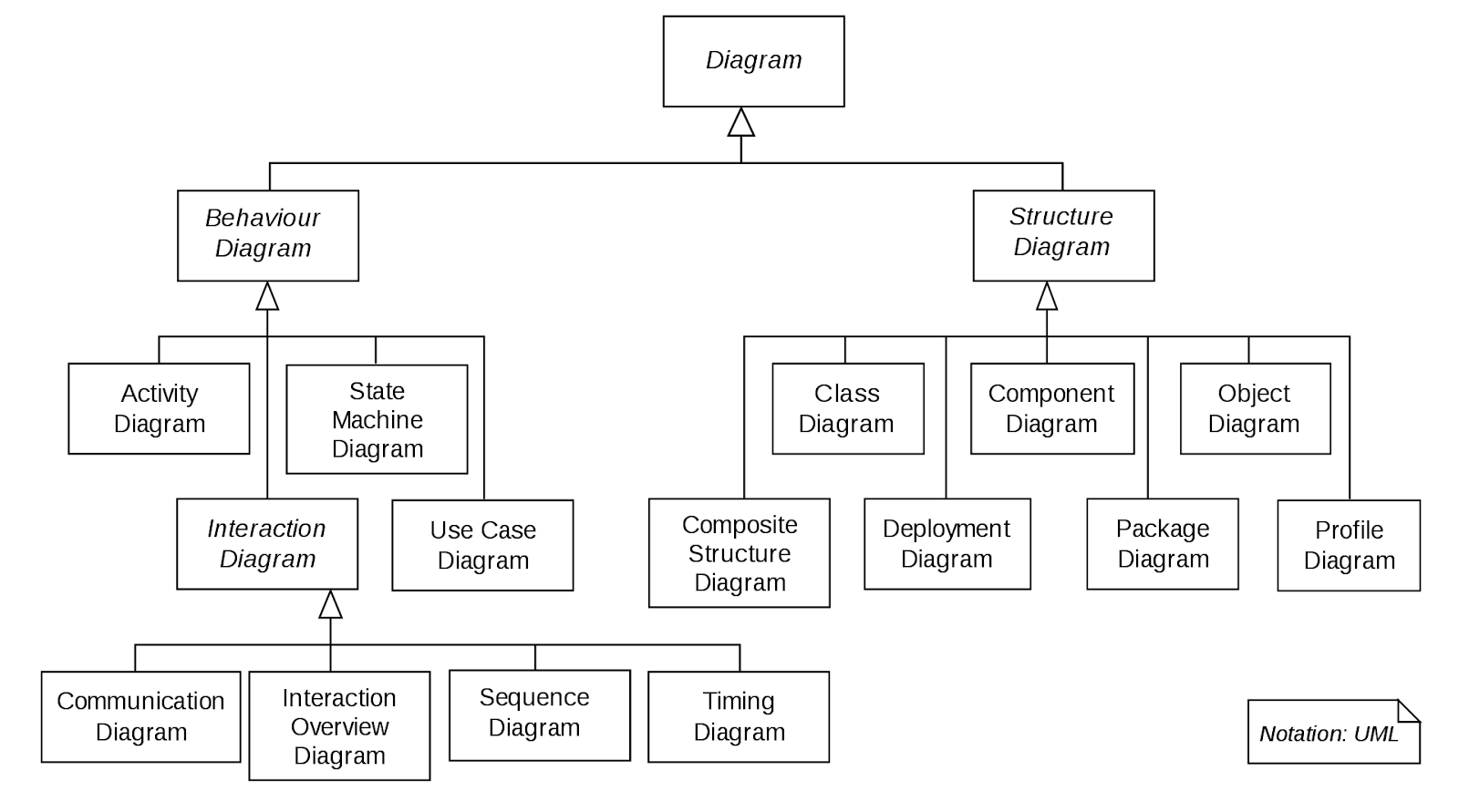
UML has many types of diagrams, which are divided into two categories. Some types represent structural information, and the rest represent general types of behavior, including a few that represent different aspects of interactions.
Class Diagram
A Class Diagram in Software engineering is a static structure that gives an overview of a software system by displaying classes, attributes, operations, and their relationships between each other. This Diagram includes the class name, attributes, and operation in separate designated compartments.
Structure diagrams
Structure diagrams show the static structure of the system and its parts on different abstraction and implementation levels and how they are related to each other. Since structure diagrams represent the structure, they are used extensively in documenting the software architecture of software systems. Structural Diagrams include: Component Diagrams, Object Diagrams, Class Diagrams and Deployment Diagrams.
Behavior diagrams
Behavior diagrams show the dynamic behavior of the objects in a system, which can be described as a series of changes to the system over time; They are used extensively to describe the functionality of software systems. Behavior diagrams include: Use Case Diagrams, State Diagrams, Activity Diagrams and Interaction Diagrams.
Interaction overview diagrams
The Interaction Overview Diagram focuses on the overview of the flow of control of the interactions.The Interaction Overview Diagram describes the interactions where messages and lifelines are hidden. You can link up the “real” diagrams and achieve a high degree of navigability between diagrams inside the Interaction Overview Diagram.

UML 2.0
UML 2.0 has been an industry standard focusing on model-driven application integration. UML 2.0 is capable of providing better semantics or definitions. It has also worked to improve the internal structuring. UML 2.0 adds the definition of formal and completely defined semantics. This new possibility can be utilized for the development of models and the corresponding systems can be generated from these models.
Unified Modeling Language – Wikipedia
What is Unified Modeling Language (UML)? (visual-paradigm.com)
